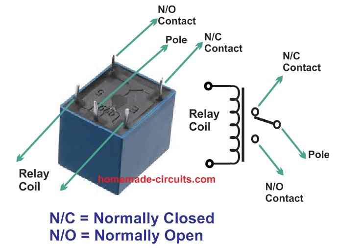
Relays come in different configurations and packages, so pin identification can vary depending on the relay type and its specific application. Here’s a general guide on identifying relay pins for common relay types:
1. Standard Electromechanical Relay Pinout
A typical electromechanical relay has five or more pins, and the configuration can include:
- Coil Pins: These are the pins used to energize the relay coil.
- Contact Pins: These are the pins used to connect the relay to the load and control circuits.
For a standard 5-pin relay, the pin configuration is usually as follows:
- Coil Pins (Pins 1 and 2):
- Pin 1 (Coil +): Connects to the positive side of the control voltage.
- Pin 2 (Coil -): Connects to the negative side of the control voltage.
- Contact Pins:
- Pin 3 (Common – COM): The common connection for the switch.
- Pin 4 (Normally Open – NO): This pin connects to the common pin when the relay is energized.
- Pin 5 (Normally Closed – NC): This pin connects to the common pin when the relay is de-energized.
2. Relay Pin Configuration
Here’s a breakdown of the pin functions for different relay types:
- SPST (Single Pole Single Throw):
- Pin 1 (Coil +): Energizing the relay.
- Pin 2 (Coil -): Ground or return path.
- Pin 3 (Common – COM): The switching pin.
- Pin 4 (NO or NC): Depending on whether it’s the Normally Open or Normally Closed configuration.
- SPDT (Single Pole Double Throw):
- Pin 1 (Coil +): Energizing the relay.
- Pin 2 (Coil -): Ground or return path.
- Pin 3 (Common – COM): The common pin that switches between NO and NC.
- Pin 4 (NO): Normally Open contact.
- Pin 5 (NC): Normally Closed contact.
- DPDT (Double Pole Double Throw):
- Pins 1 and 2 (Coil): Energizing the relay.
- Pins 3 and 4 (COM1 and COM2): Common contacts for the two poles.
- Pins 5 and 6 (NO1 and NO2): Normally Open contacts for the two poles.
- Pins 7 and 8 (NC1 and NC2): Normally Closed contacts for the two poles.
3. Pin Identification Tips
- Datasheet: The most accurate way to identify relay pins is by consulting the relay’s datasheet. The datasheet provides detailed information about pin functions, voltage ratings, and other specifications.
- Relay Labeling: Many relays have pin numbers or labels printed on their case. Use these labels to correctly identify each pin.
- Continuity Testing: Use a multimeter to test continuity between pins. By energizing the coil and measuring continuity between pins, you can determine which pins are connected in different states.
- Relay Symbol: Understanding the schematic symbol of the relay can help in identifying the pin functions. For example, the symbol will show the coil and the contact arrangement.
- Visual Inspection: In some cases, visual inspection of the relay’s internal construction can help determine the pinout, especially for simple relays.


