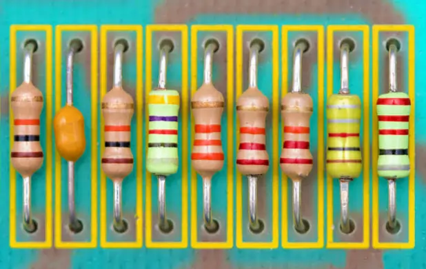
Tutorial 1
Electronic construction demands certain fundamental knowledge of different electronic components like resistors, capacitors, transistors inductors, and so on. Resistors are one of the fundamental components of electronic circuits. Whether you are a beginner or an experienced hobbyist, understanding how resistors work is crucial for circuit design analysis.
If you open any electronic devices or gadgets you will see a variety of resistors. Actually, they are the most common components in electronics and contribute significantly to the total number of components counts.
In this article, we will explore different fundamentals of resistors and the basics you need to know about how resistor works before beginning the electronics journey.
So, what is a Resistor?
A resistor is a passive electronic component that is extensively used for limiting or regulating the flow of electric current through electronic or electric circuits. The main purpose of a resistor is to limit the flow of electric current.
In electronics, the term passive means that do not generate or amplify electrical signals, rather they only consume or store energy. In other words, components that do not require an external power supply to operate. Resistors, capacitors, and inductors are some examples of passive components.
How Resistors Work?
In electronics, we want to control the flow of current preciously for proper functioning of electronics components and resistors play a crucial role in this process.
To understand how a resistor works let’s imagine electric current as vehicles that you are driving along an open highway. Voltage is the force that pushes the vehicles similar to the power of the engine and resistors as narrow lanes that slow down the traffic.
In this analogy we assumed
- Electric Current is the flow of vehicles
- Voltage is the force that pushes the cars forward, similar to the power of the engine.
- Resistors are like narrow lanes that slow down the traffic.
Now, based on this scenario, in your analysis you may come across three traffic states, smooth traffic, restricted traffic, and Controlled traffic.
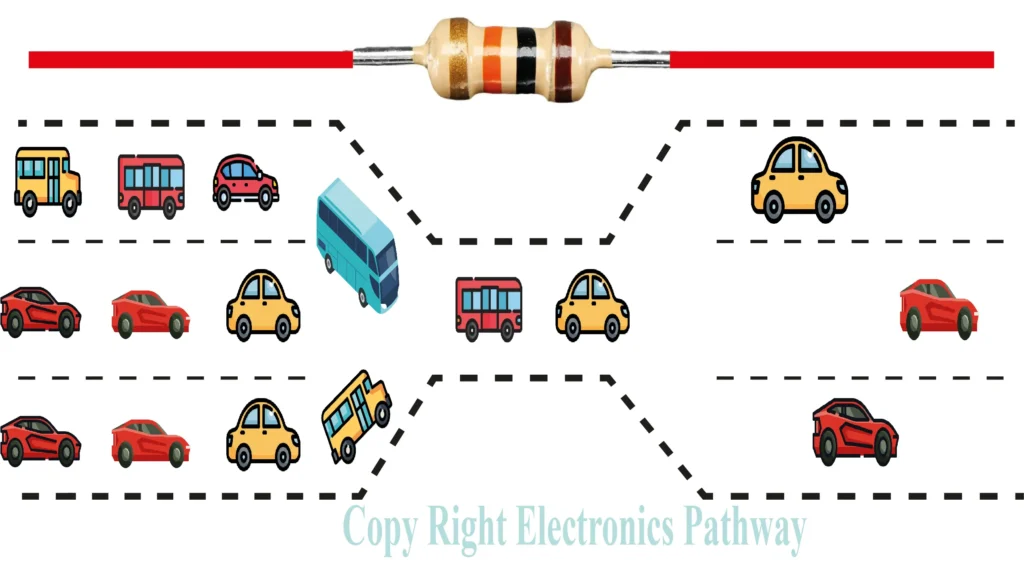
- Smooth Traffic (Low Resistance):
- On wide and open highways with multiple lanes as shown vehicles can travel quickly and freely. This is similar to a circuit with low resistance, where current can easily flow.
- Restricted Traffic (High Resistance):
- When the highway is narrow majority of vehicles have to slow down and only a few vehicles can pass at a time. This is similar to a circuit with high resistance where electric current is restricted to flow easily.
- Controlled Traffic (Adjustable Resistance):
- If the junction width can be adjusted then we can control the flow of traffic if the junction can be made wider then more vehicles can flow and if the junction is made narrow controlled number of vehicles can only flow. Which is similar to the amount of current flowing through the circuit.
Now, if we assemble this information in a more engineering approach we can define it.
- Voltage is analog to the engine power that pushes the electrical current.
- Resistor is analogus to width of lanes that controls how many vehicles can pass through it.
- Current is similar to the vehicles speed that travels smoothly if there is less resistance and slows down where there is more resistance.
Ohm’s Law
Now, after understanding how resistors work, let’s define this relation in a more formal way and a more engineering approach. The relationship between voltage, current, and resistance in an electric circuit was discovered in 1826 by Georg Simon Ohm. This relationship is also known as ohm law. According to ohms law:
The amount of current flowing in the circuit is directly proportional to the amount of voltage applied and inversely proportional to resistance.
Mathematically it can be expressed as:
$I=\frac{V}{R}$
If we arrange it in other way we get
$
V=I . R
$
Unit of Resistor
Realizing the contribution of physicist Georg Simon Ohm the unit of resistance is measured in Ohms (Ω).
Resistor Symbols
If we look at the circuit diagram we primarily see two types of symbols for resistors. These symbols vary slightly based on the standard used. Broadly speaking these standards are of two types IEC (International Electrotechnical Commission) standard and ANSI (American National Standards Institute) standard.
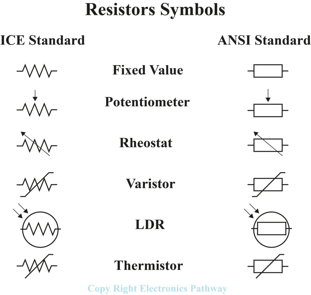
Even though both of these symbols are extensively used the primary concept of the resistors remains the same. Some resistors have fixed value while other resistance can be changed. Some of the major types of resistors and its symbol in both formats is shown below. Now don’t be confused with the symbol as you may find circuit design in both formats around the web.
Why Are Resistors Important?
After understanding the basics and how resistors work and their symbols let’s understand why are they so important in electronic circuits.
1. For Controlling the Flow of Current
Different electronic components like LEDs, transistors, and integrated circuits have pre-defined current requirements. If too much current flows through them they can be damaged or destroyed. To limit the current flow through them and to protect these components resistors are extensively used.
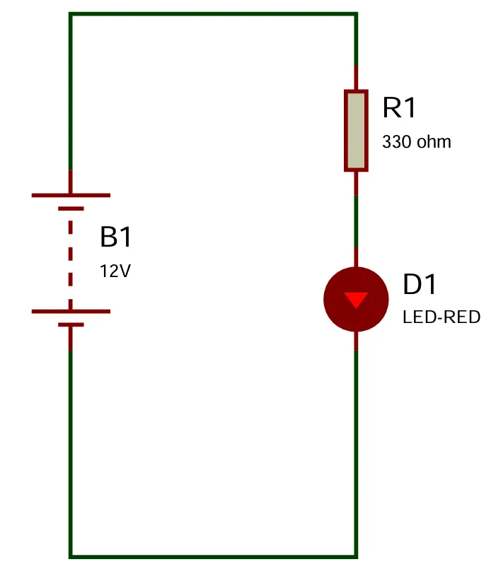
Here, the source is a 12V battery if the LED is connected directly to the source, the LED will burn out or get destroyed. To solve this problem a resistor of 330 ohms is used which can limit the flow of current through the resistor.
2. For Voltage Division
Resistors are also extensively used for voltage division purposes. When combined in series the resistor divides the voltage into precise levels needed by different parts of a circuit.
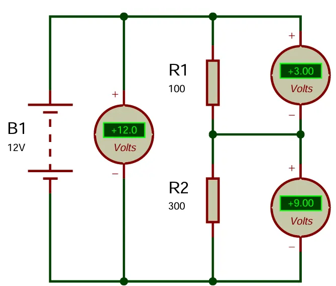
Here, we have arranged two 100-ohm and 300-ohm resistors in series. Even though the supply voltage is 12V the voltage across the resistors is divided into 3V and 9V respectively. So, when you have a source of fixed voltage you can choose appropriate resistors to get the required voltage levels.
3. For Signal Conditioning
Similarly, resistors in combination with capacitors or inductors are also used in filtering unwanted signals or noises from signals. Such application is crucial in audio processing like radio communication or signal modulation.
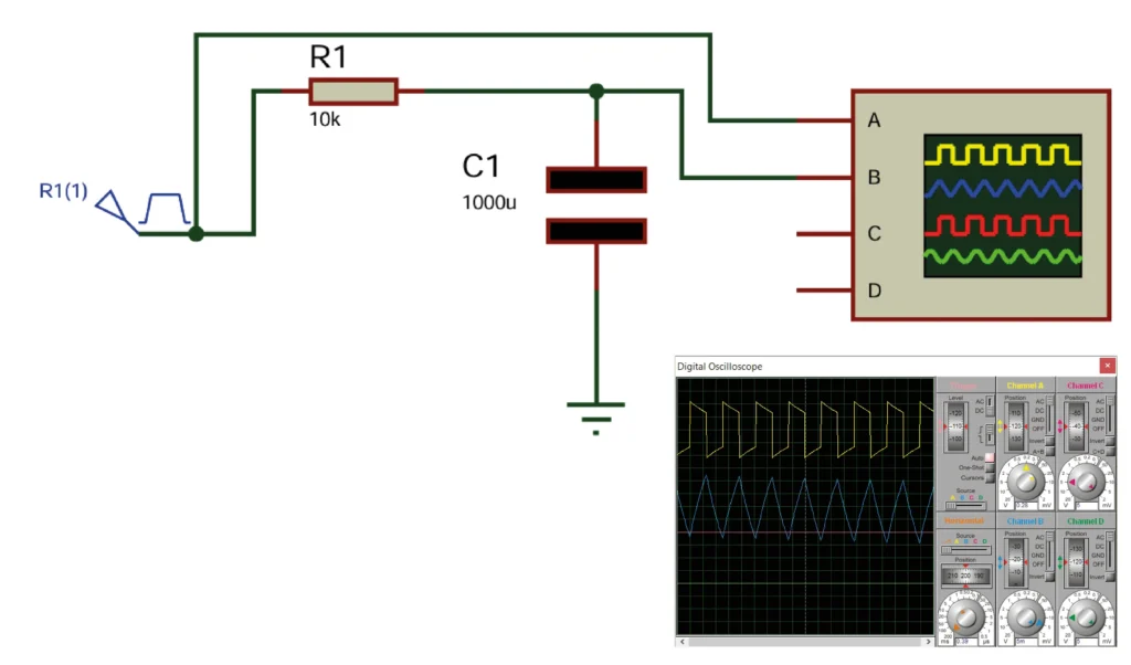
Here, if we see the simulated graph the input signal is like a square wave but if we observe the output wave across the capacitor it is similar to a triangular shape. Here the square part is filtered and only low signals are passed.
4. For Biasing Active Components
In a circuit where transistors are involved, resistors are used to form a voltage divider and is connected to the base of the transistors. Such an arrangement provides a fraction of the source voltage to the base of the transistors to remain in the desired operating regions. These operating regions can be active regions or saturation/cutoff regions.
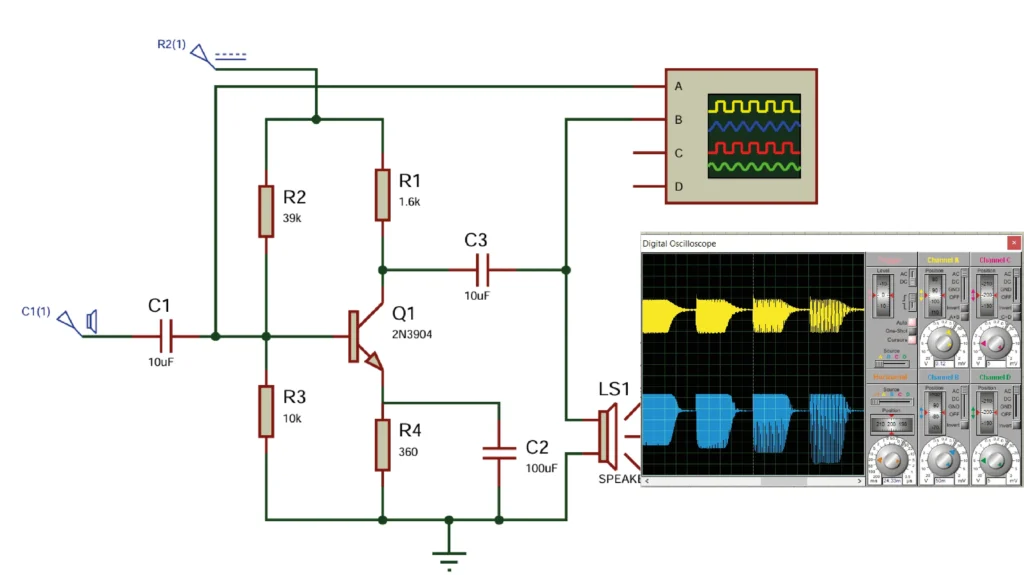
Here in this circuit two resistors R1 and R2 are connected in series to form a voltage divider circuit. This circuit divides the source voltage and only a fraction of the source voltage is applied to the base of the transistor. This voltage circuit along with emitter resistors is added further to improve the performance of the operation.
Such circuits are extensively used in amplification circuits. Here, if we see the input signal and output signal the output audion signal is amplified by the transistors gain. Even though there are some distortion, this is basic example of single stage amplifier. The yellow wave is the audio input signal and the blue waves are amplified audio signals.
5. For Energy Dissipation
Resistors also play a crucial role in converting electrical energy into heat energy. Such property of resistors makes them useful in heating elements. In other cases, resistors are also used as dummy loads. A dummy load is used to dissipate excess energy in the circuit to protect more sensitive and critical components from potential damage from high currents.
6. For Pull-up and Pull down
In digital circuits, particularly in microprocessor or microcontroller circuits, the pins can be in different states: input state, output state, and floating state. A floating state means the pin is not connected to a definite voltage level making any input from an external source unpredictable and potentially leading to erratic outputs.
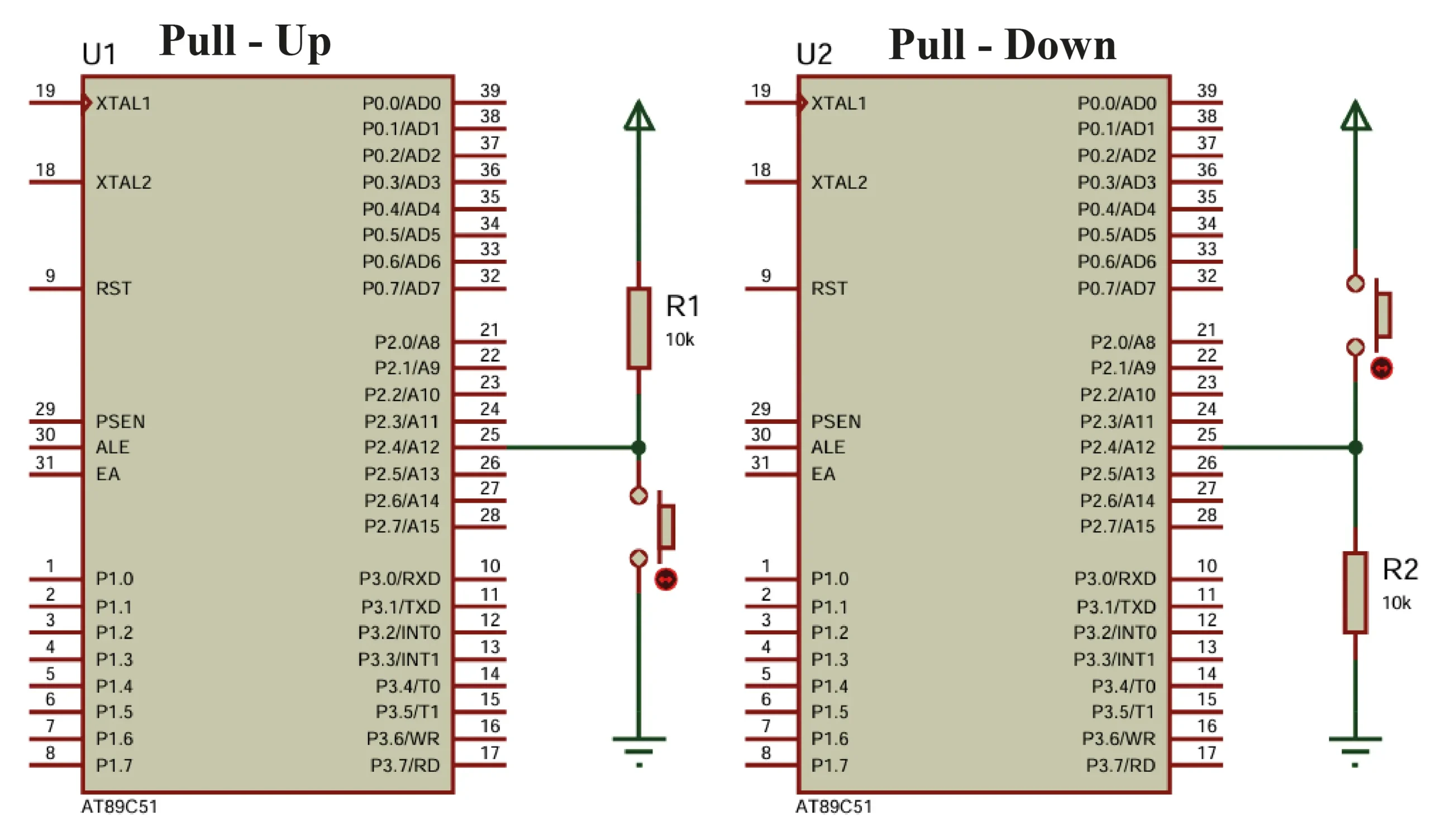
To prevent such a scenario the pins of the microcontroller are brought to a known state i.e. either a low state or to high state. To address these resistors are used as pull-up or pull-down configurations.
Pull-Up Resistor
If a resistor is used to connect the microcontroller pin to a higher voltage level(usually the supply voltage level VCC), then it is called a Pull-Up configuration. Such a technique ensures that the pin of the microcontroller is at a high logic level when no other external signal is attached to it.
Pull-Down Resistor
Conversely, If a resistor is used to connect the microcontroller pin to a lower voltage level(usually the ground voltage level Gnd), then it is called a Pull-Down configuration. Such a technique ensures that the pin of the microcontroller is at a low logic level when no other external signal is attached to it. This mechanism stabilizes the input and makes the system reliable and predictable.
Conclusion
Resistors are simple components of the electronics world however they play a pivotal role in circuit design. Understanding the fundamentals is necessary for a successful journey to the world of electronics. Here, we learned the fundamentals of resistors, its symbol, and its application. In the next section, we are going to dive deeper into the world of electronics and learn different types of resistors and how to read resistor values.

